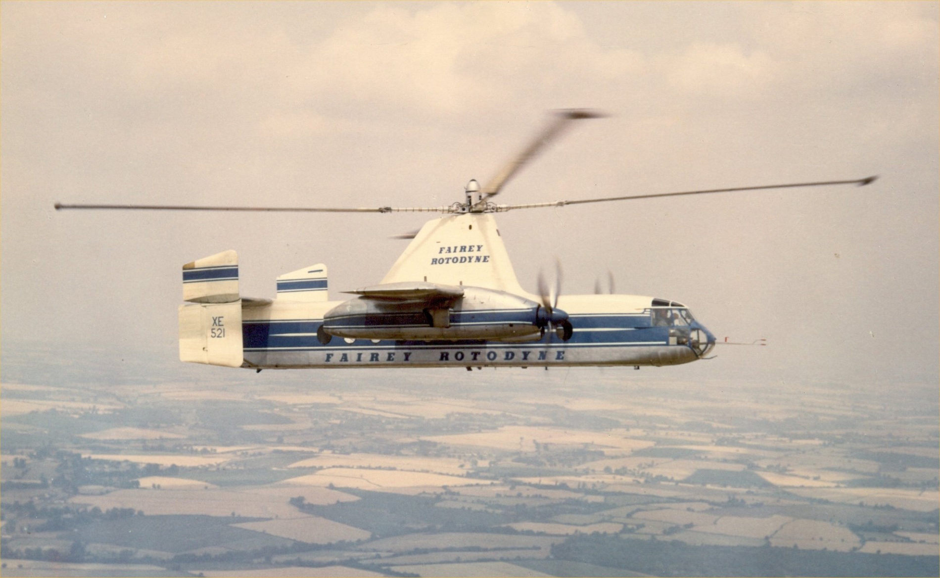
At the beginning of the Superman TV shows the question was “Is it a bird? Is it a plane? No, its Superman”: and in the case of the Fairy Rotodyne we could ask “Is it a helicopter? Is it a plane? No, its a Rotodyne.
But then we must ask the question “What is a Rotodyne?”
The Fairy Rotodyne was a brilliant concept, it was indeed not a helicopter, nor was it a plane, but instead it combined the essential design of an autogyro with a plane to produce what maker Fairey decided to call a Rotodyne.
An autogyro has a helicopter like rotor but that rotor is not driven by an engine, instead as the aircraft gains speed the air causes the rotor blades to rotate, and that is what causes the craft to lift off from the ground and fly.
This means that an autogyro must have a separate powered propeller to give it horizontal thrust to take the aircraft up to a speed which in turn causes the rotor to spin and create lift.
So an autogyro cannot take of vertically like a helicopter: in order to lift off vertically the blades of the vertical rotor must be powered to create the same sort of lift as a helicopter uses.
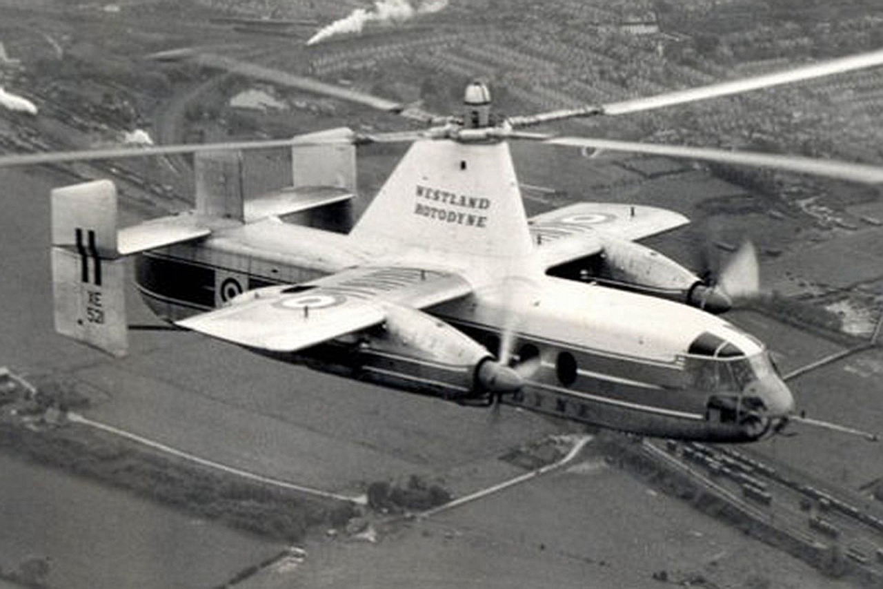
The Rotodyne’s vertical rotor was not connected to an engine, but instead on the end of each of the four rotor blades was installed a “tipjet”. To each of these tipjets was fed compressed air and fuel via three tubes incorporated into each rotor blade. When the fuel-air mix was ignited each tipjet became like a miniature rocket engine and despite their very small size they were able to spin the rotor blades with adequate power to cause the aircraft to take off like a helicopter.
The Rotodyne was equipped with relatively short wings and a tail with rudders much like a conventional aircraft, and it had twin turboprops driven by gas turbine engines which both spun the propellers used for horizontal flight and provided the compressed air and fuel to the tipjets.
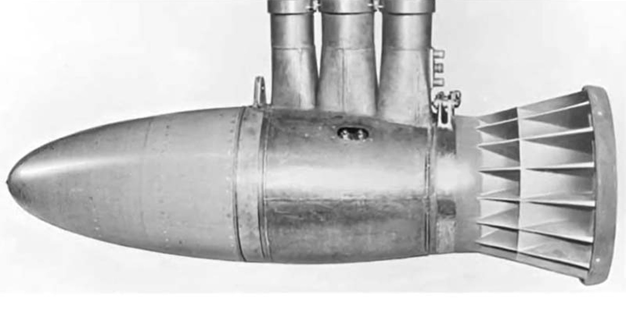
As you will readily understand, in order for the Rotodyne to fly it requires two phases of flight; the first being for vertical take-off, which uses the tipjets, and then the pilot must make a changeover to horizontal flight for which the turboprop engines give the aircraft sufficient forward speed to spin the autogyro blades to provide the lift required, at which point the tipjets are extinguished as they are not needed at that point.
In order to land the Rotodyne the reverse process was required: in other words the aircraft speed needed to be reduced to the point where the tipjets could be re-ignited and progressively take over the role of driving the main rotor to provide the needed vertical lift, then the aircraft could be landed much like a helicopter.
Development History
The original idea for the Rotodyne was to provide quick and convenient travel between city centres, such as from London in Britain to Paris, France for example. The aircraft needed to be VTOL (Vertical Takeoff Or Landing) and able to carry enough passengers to bring the cost per passenger mile down to the point where it was economical both for passengers and the companies that operated the aircraft.
The initial idea which led to the vision for the Rotodyne was from Dr. J.A.J. Bennett, who was Chief Technical Officer for the Cierva Autogiro Company from 1936-1939. At the end of the Second World War in 1945 Dr. Bennett joined the British Fairey aircraft company and was put to work developing his ideas for rotorcraft as head of the company’s rotary wing aircraft division.
The first design to emerge from Dr. Bennet’s division was the FB-1 Gyrodyne which had an Alvis Leonides 522/2 radial engine mounted in the middle of the fuselage, whose drive was used for both the main rotor just as in a helicopter, and a horizontal thrust propeller mounted at the end of a small wing on the right side of the aircraft.
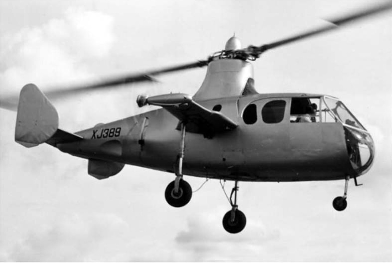
The second prototype was the Fairey Jet Gyrodyne which was based on the FB-1 design but with two short wings instead of one, and push propellers for horizontal thrust on each wing.
The Alvis Leonides radial engine drove a pair of superchargers as used in the famous Rolls-Royce Merlin engines that for example powered Britain’s Spitfire and other wartime aircraft.
These superchargers were used to send compressed air through integrated pipes in the twin rotor blades to pressure jets (i.e. tipjets), where the compressed air and fuel mix was ignited and then powered the main rotor’s blades to provide the vertical lift: just as would later be used on the Rotodyne.
The kickstarter for Fairey to embark on the program to develop a commercial rotorcraft came in 1951-1952 when British European Airlines created the specifications for a Vertical Takeoff Or Landing airliner which they called the “BEA-bus” (Bealine-Bus), which could do short haul flights between major cities and do vertical takeoffs and landings at heliports conveniently placed in the midst of those cities. This in turn caught the attention of the British Government’s Ministry of Supply (MoS), who were in charge of procuring new designs for equipment that would be valuable to Britain’s armed forces.
The Ministry of Supply sponsored a number of studies not only to help BEA, but to encourage private enterprise to engage in research and development of technologies that would be of value to the British Military.
Of the many submissions to the MoS were a number from Fairey, and when evaluated by the MoS one Fairey design was thought to be practical, useful, and achievable. As a result Fairey was awarded a contract to produce a prototype Rotodyne for the Ministry of Defense in 1953.
Fairey then proceeded to work on creating a working prototype which they referred to as the “Rotodyne Y”, which they would ultimately manage to build successfully.
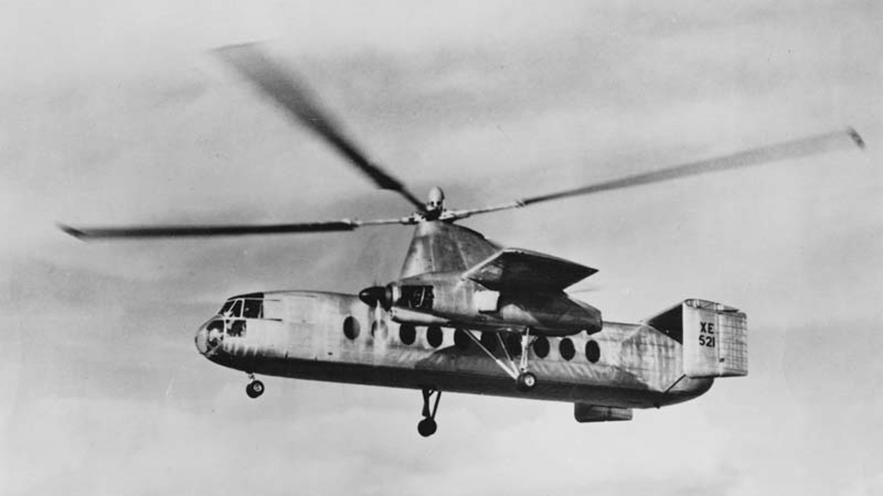
One of the early problems Fairey had to overcome was in sourcing suitable engines. Rolls-Royce were already somewhat over committed having a number of projects to take care of, many of them military and high priority: so they were not able to provide for the Rotodyne.
Fairey finished up selecting the Napier Eland N.El.3 turboshaft, equipped with auxiliary compressors for the four tipjets.
These engines were installed into the approximately 33,000 lb Rotodyne Y prototype which was designed with a passenger carrying capacity of 40-50 passengers, an expected cruising speed of 150 mph, and range of 250 Nautical miles (460 km).
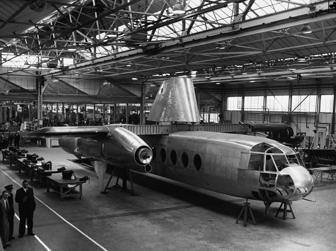
All looked promising but the first spanner to be thrown into the works occurred in 1956 when the Defence Research Policy Committee decided that there would be no interest in the Rotodyne Y by the British Military. The funding for the project was however continued into 1957.
Testing of the prototype began on 6th November 1957 with the Rotodyne’s maiden flight. It took until 10th April 1958 before the first successful transition from vertical to horizontal flight modes and back to vertical was made.
On 5th January 1959 the Rotodyne prototype began to demonstrate its abilities by setting a “convertiplane” world speed record of 190.9 knots (302.7 km/hr). It’s abilities were demonstrated at both the Farnborough air show in Britain and the Paris air show where it showed it could hover with one engine shut down and propeller feathered.
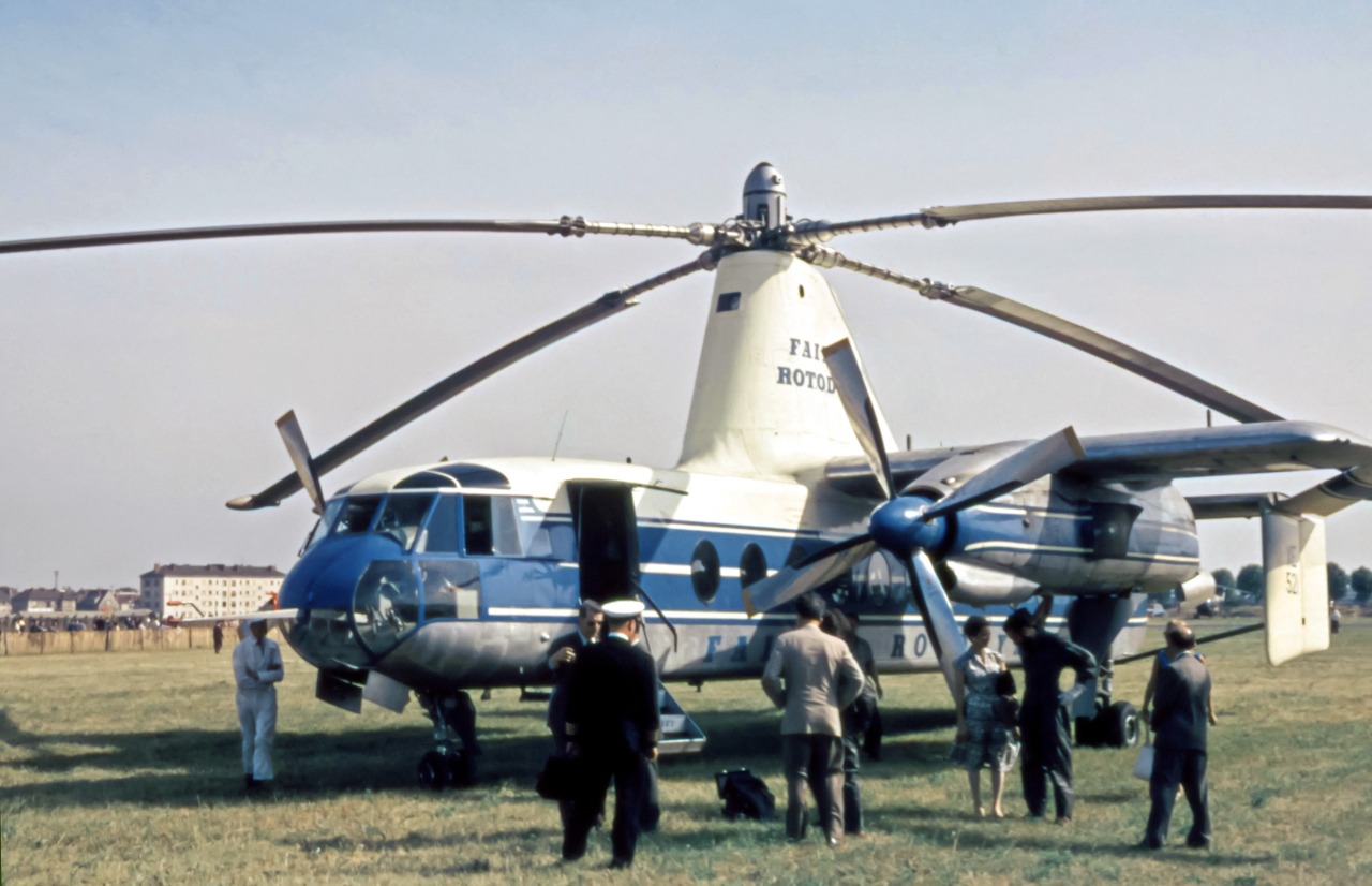
The Rotodyne Y prototype was able to demonstrate lively aerobatic ability by executing a steep climbing turn at 175 mph, and it once showed off its lifting abilities by lifting a 100 foot long girder bridge.
Potential buyers were impressed with the prototype’s performance and both military and civilian customers expressed interest in acquiring the Rotodyne including the Royal Air Force who said they’d buy a dozen, British European Airways who said they’d like half a dozen, New York Airways was interested in five, with an option to buy fifteen more, and Uncle Sam’s US Army thought it might be willing to take a couple of hundred.
As it turned out however one major problem stood in the way of the Rotodyne’s widespread adoption, and that was the problem of noise from the tipjets. An aircraft that is to operate in and out of a city centre had to be sufficently quiet to not cause public complaints, and the tipjets fitted to the Rotodyne Y generated 113 Db at 600 feet (180 metres), with one test pilot claiming that the noise would “stop a conversation at a distance of 2 miles.
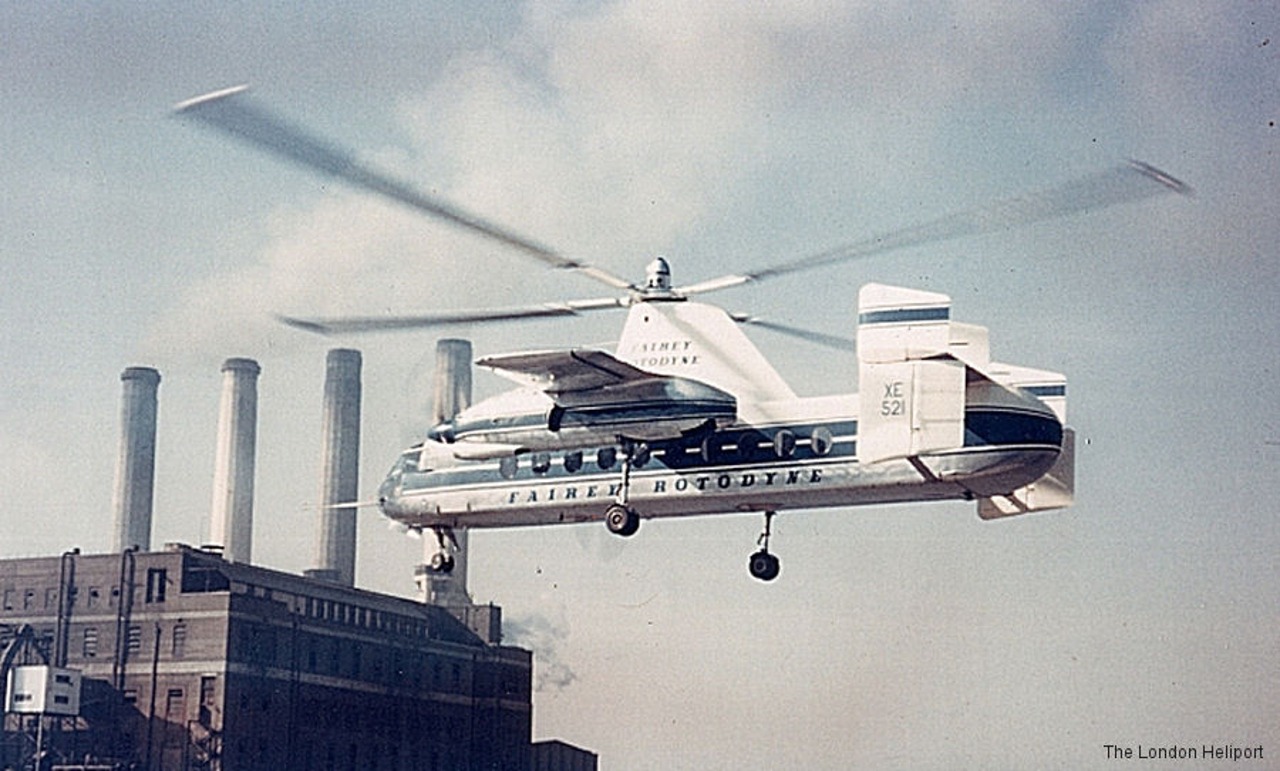
The fact that the Rotodyne Y prototype made a couple of flights into and out of the London Battersea heliport without precipitating any complaints seems to indicate that the noise was perhaps not as dreadful as some claimed, but it was enough to greatly dampen the enthusiasm of potential buyers.
Fairey engineers were able to bring the tipjet noise down to 96 Db at 600 feet but despite that, and the probability that the noise could be reduced further, government funding was terminated in early 1962 and then BEA stated that they would not be ordering Rotodyne’s because of the noise issue, and the project collapsed.
The Rotodyne Y prototype was mostly scrapped with just a section of fuselage finding its way into the Helicopter Museum in Weston-super-Mare along with the rotorhead mast and rotors. It was an inglorious end for an aircraft that demonstrated superb performance. Had it succeeded it could have dramatically changed intercity travel in Europe, in the United States, and in many places across the world.
Technical Information
- Crew: two
- Capacity: 40-48 passengers
- Length: 58 ft 8 in (17.88 m) of fuselage
- Wingspan: 46 ft 6 in (14.17 m) fixed wings
- Height: 22 ft 2 in (6.76 m) to top of rotor pylon
- Wing area: 475 sq ft (44.1 m2)
- Airfoil: NACA 23015
- Empty weight: 22,000 lb (9,979 kg)
- Gross weight: 33,000 lb (14,969 kg)
- Fuel capacity: 7,500 lb (3,402 kg)
- Powerplant: 2 × Napier Eland N.El.7 turboprops, 2,800 shp (2,100 kW) each
- Powerplant: 4 × rotor tip jet , 1,000 lbf (4.4 kN) thrust each
- Main rotor diameter: 90 ft 0 in (27.43 m)
- Main rotor area: 6,362 sq ft (591.0 m2) Rotor aerofoil: NACA 0015
- Blade tip speed: 720 ft/s (219 m/s)
- Disc loading: 6.14 lb/ft2 (30 kg/m2)
- Propellers: 4-bladed, 13 ft (4.0 m) diameter Rotol propellers
Performance
- Maximum speed: 190.9 mph (307.2 km/h, 165.9 kn) speed record
- Cruise speed: 185 mph (298 km/h, 161 kn)
- Range: 450 mi (720 km, 390 nmi)
- Service ceiling: 13,000 ft (4,000 m)
(Technical information courtesy Wikipedia compiled from “Data from Fairey Aircraft since 1915” by Hugh A. Taylor, “Autogyros, Gyrocopters, & Gyroplanes” by Greg Goebel 2015, “Leading particulars of Rotodyne Type ‘Y'” Gibbings 2011, and “Jane’s All the World’s Aircraft 1958-59”.)
Jon Branch is the founder and senior editor of Revivaler and has written a significant number of articles for various publications including official Buying Guides for eBay, classic car articles for Hagerty, magazine articles for both the Australian Shooters Journal and the Australian Shooter, and he’s a long time contributor to Silodrome.
Jon has done radio, television, magazine and newspaper interviews on various issues, and has traveled extensively, having lived in Britain, Australia, China and Hong Kong. His travels have taken him to Indonesia, Israel, Italy, Japan and a number of other countries. He has studied the Japanese sword arts and has a long history of involvement in the shooting sports, which has included authoring submissions to government on various firearms related issues and assisting in the design and establishment of shooting ranges.

