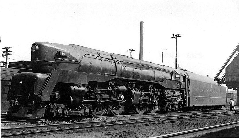
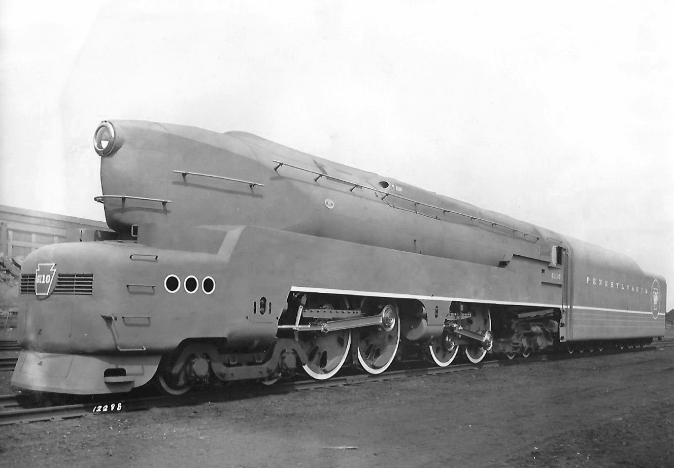
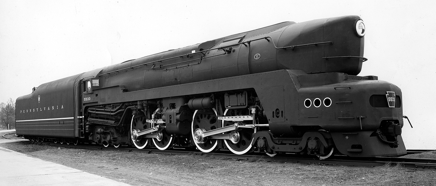
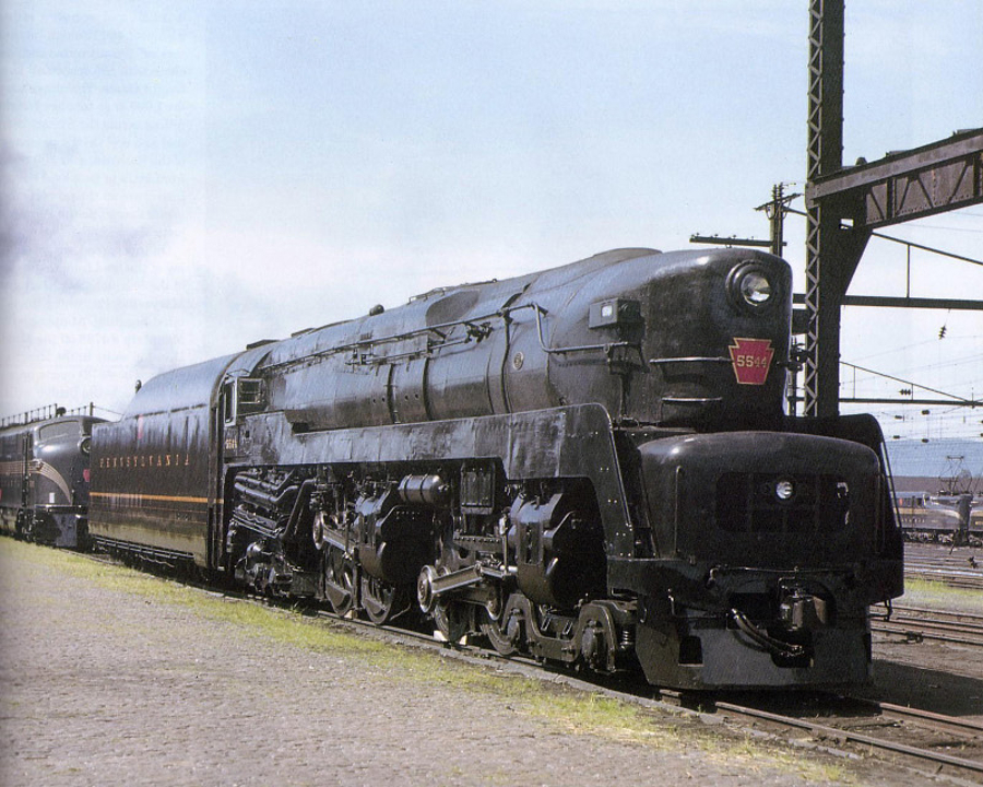
The Pennsylvania Railroad’s T1 duplex steam locomotive is perhaps the most eye-catching, and the most controversial ever created. Engineers at the Pennsylvania Railroad (PRR) and at Baldwin Locomotive Works created a quite complex solution to building a reciprocating steam locomotive with enormous power and the ability to cruise at 100mph. This engineering masterpiece was then given, as a crowning glory, streamlining created by Raymond Loewy, America’s master of industrial design. What was produced was a steam locomotive that not only looked like a missile on wheels, but that performed like one.
Background – Dynamic Balance and the Atlantic Coast Line R-1
The background to the creation of this rail-going missile is a bit of a complex story, but it’s not too difficult to fit the pieces of the puzzle together to figure out why the engineers decided to create this relatively complex steam locomotive.
As the 1930’s progressed a number of American railroads were confronted with dramatically increased demand for passenger traffic: three examples being the New York Central, its rival the Pennsylvania Railroad, and the Atlantic Coast Line. The New York Central’s strategy to cope with the increased train weights was to build bigger and better Hudsons (locomotives with a 4-6-4 wheel arrangement), and then Mohawks (having a 4-8-2 wheel arrangement and more tractive power), finishing their development efforts with the Niagara (Very large and powerful locomotives with 4-8-4 wheel arrangement). Faced with the exact same problem set the Pennsylvania Railroad adopted a very different strategy, and it may have been the lessons learned by Baldwin Locomotive Works on the Atlantic Coast Line that led to the PRR doing what it did.
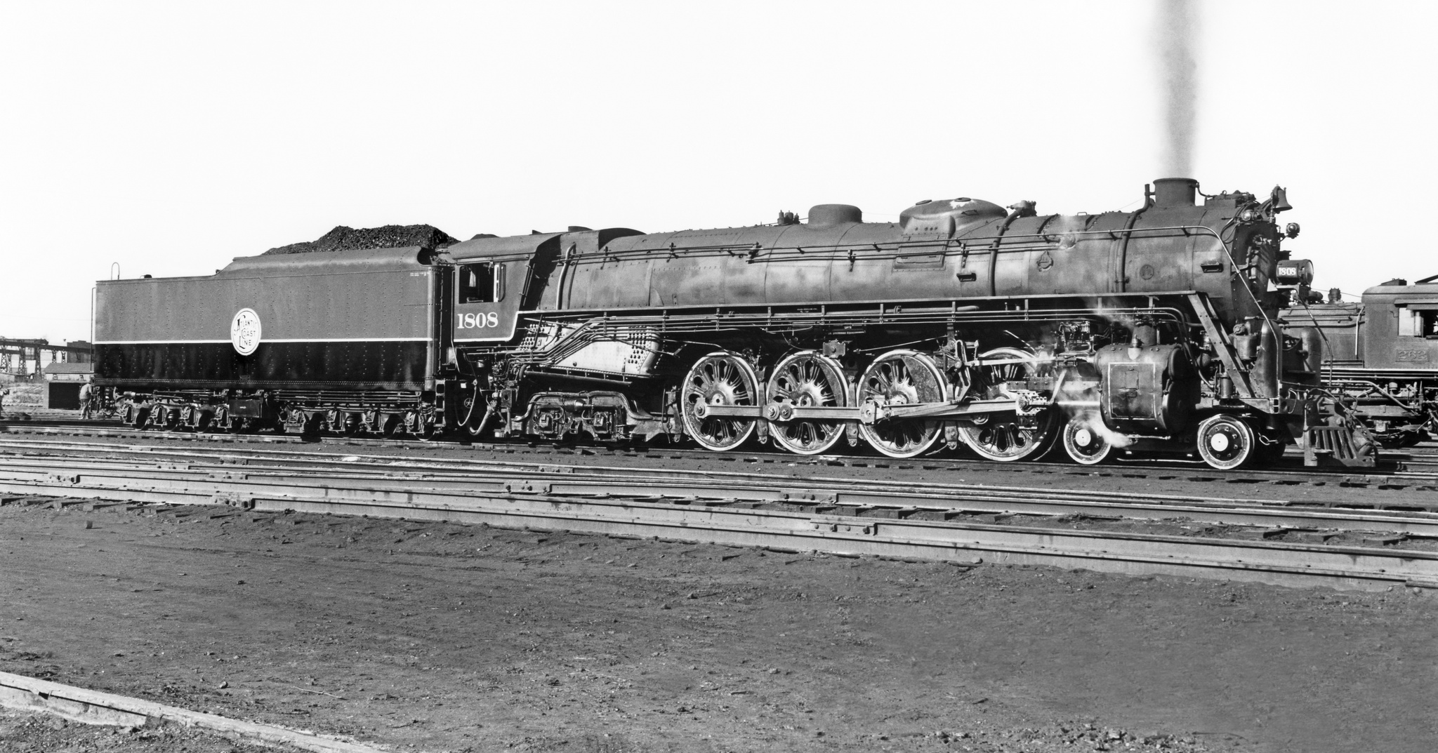
The story begins in the late 1930’s at the Atlantic Coast Line (ACL). Passenger traffic on the ACL between Richmond, Virginia and Jacksonville, Florida had become so heavy that the company were forced to double-head their passenger trains. Double-heading means to use two locomotives to pull the train because one will not suffice. The ACL’s passenger engines were old USRA (United States Railroad Administration) standard 4-6-2 Pacific locomotives and they were due for modernization. Double-heading a train requires not only two steam locomotives but also two crews to drive them, doubling wage costs. Management at the ACL decided to go for the best that the Baldwin locomotive works could offer them and so they went for an upgrade to full-sized 4-8-4 Northern locomotives with great power and speed potential. Baldwin’s engineers did their mathematical calculations and were confident that the 4-8-4 locomotive that would be called the R-1 would perform perfectly. These locomotives must have looked amazing on the drawing board because they looked even more magnificent when built and painted in the ACL’s attractive two tone gray color scheme.
When the R-1 locomotives entered service however it did not take long before the specter of track damage reared its ugly head. The engineers at Baldwin were perplexed, their calculations were correct according to all that 1930’s technology had taught them. But there were clearly problems of dynamic balance that they had not encountered before and what was happening was that the reciprocating forces were so out of balance that the locomotive’s driving wheels were literally lifting off the track and then hammering down on it, causing expensive damage. This problem was no doubt exacerbated by the locomotive drivers/engineers who were pushing these amazing new locomotives at speeds up around 100mph despite the fact that they had been instructed not to take the R-1’s above 80mph.
Baldwin engineers came up with a solution to the problem which required fitting of lightweight reciprocating parts and revising the dynamic balance: but the damage was done, not only to Baldwin’s reputation, but also to the reputation of steam locomotives in general. The Atlantic Coast Line relegated the R-1 locomotives to freight use and went out and bought themselves nice new diesel locomotives that would not hammer track.
Design Decisions for the Pennsylvania Railroad T1
So it was when the Pennsylvania Railroad approached Baldwin with ideas for a new high power, high speed steam locomotive the idea that was favored was to use a duplex wheel arrangement that would group the eight driving wheels into two groups of four. This reduced the reciprocating mass of parts significantly, for example by eliminating the section of the main connecting rod between the second and third driving wheels and thus reducing that mass by a third. Similarly the pistons were much smaller because there were four of them instead of two. In addition to this the Pennsylvania Railroad already had some experience with duplex passenger locomotives, particularly their S1 prototype which also had eye catching streamlining by Raymond Loewy.
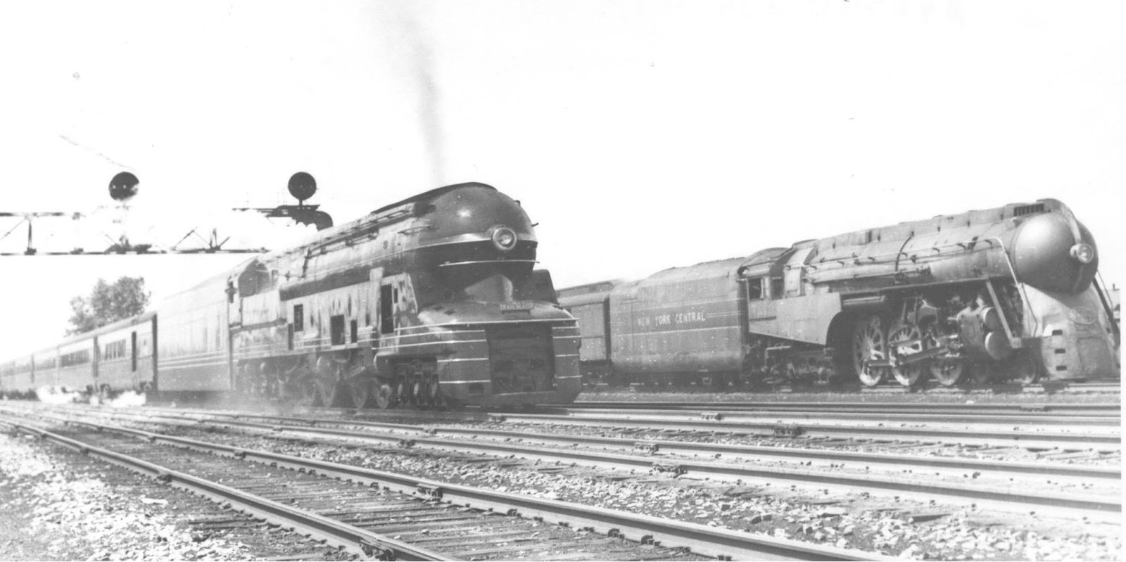
The engineers and management at Baldwin were also without doubt aware of the competition they were up against from the new diesel locomotives, and they wanted to go with what they perceived to be the best, and hopefully the safest option. But when you are working with new technical solutions it is unlikely you will get all the answers right on the first attempt. The plans were drawn up and the first two “missile on wheels” T1 duplex locomotives, numbers 6110 and 6111, were constructed at the Baldwin Locomotive Works.
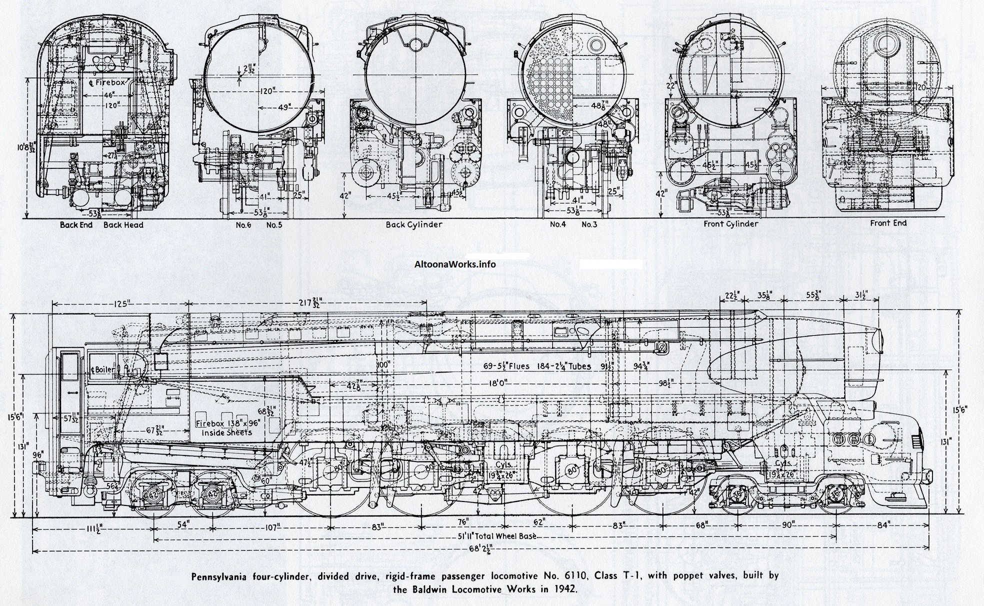
(Note: To see the full range of maps and locomotive drawings at altoonaworks.info click here).
These first two T1 locomotives were put through a thorough evaluation once they were delivered to the PRR and the results were glowing. So confident in these reports were management that they placed an order for another fifty T1’s, of which 25 would be built by Baldwin between 1942-1946 (Nos. 5525-5549), and 25 built by the Pennsylvania Railroad at their own Altoona workshops between 1945-1946 (Nos. 5500-5524).
The T1 in Service: Early Teething Problems
As these locomotives entered service and started to earn their keep both the advantages and the disadvantages of the design began to show up. The speed and power of the T1’s more than lived up to expectations. They had been designed to deliver 100mph speeds with heavy passenger trains and they proved more than capable of doing so. Not only did they look like rail-born missiles but drivers soon discovered that they could perform like a missile as well. A technician who had been given the job of trouble-shooting problems with the T1’s poppet valves discovered drivers getting them up well north of 120mph: in fact he observed speeds up to 140mph with drivers who were trying to make up time. In order to assess this accurately he would have had to have been using a stop watch over known distances as the T1’s speedometer only went up to 120mph. Essentially this was partly the same problem as had been experienced on the Atlantic Coast Line: give a driver/engineer a powerful high speed locomotive and you can tell them to limit their speed – but, when the tracks are long and management is far away he’s likely to want to open up the throttle and find out what she’ll really do. Boys will be boys.
You’ll find a great story by a train crew member on just such a “making up time” situation if you click here. Reading it I wish I’d been on the footplate with them.
This short video from The T1 Trust provides a glimpse of what the T1’s looked like in service, and we can imagine the temptation for the engineers/drivers to “see what she’ll do”.
[arve url=”https://www.youtube.com/watch?v=znMu4K71ktY” /]
The Front Driver Wheel-slip Issue and its Solution
Once the T1’s were in regular service with normal crews driving them some problems emerged. The most famous of these is the propensity for the front driving wheel group to slip, and an example of that occurring can be seen in the video above. This did not only occur at slow speeds such as when starting off, but would also manifest itself at high speeds in which case it was violent and extremely difficult to control. This problem was a factor in causing mechanical failures. There are two likely causes for this problem, and it would appear that both were solved. The first likely cause was that the spring equalization was not correct. When new the T1’s had their driving wheel springs equalized together, and not equalized with the trucks that supported the weight of the locomotive at the front and rear. To solve the wheel slip problem engineers changed the spring equalization so that the front set of driving wheels was equalized with the front truck that supported it, and the rear set of driving wheels with the rear truck that supported it. Evidence suggests that this at least ameliorated the problem and quite possibly fixed it.
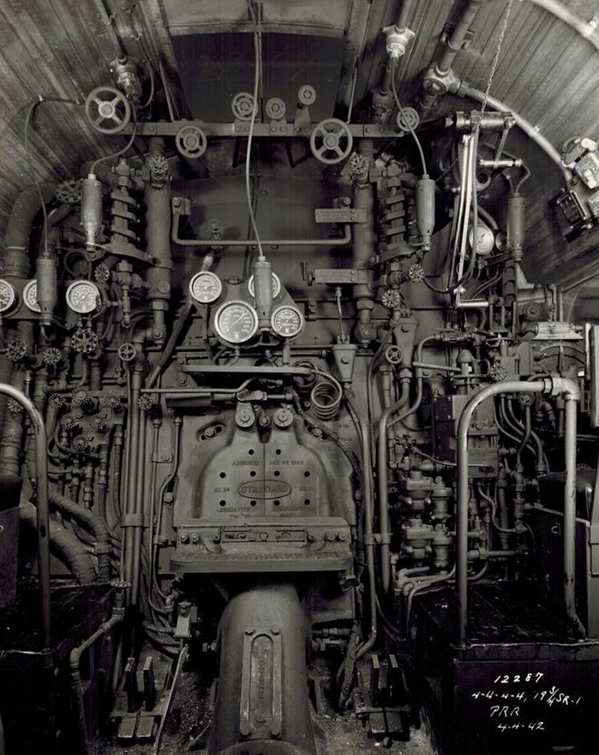
The adjustment of the spring equalization was one of a number of modifications made to T1 locomotives during their service. Evidence that modifications such as the change to the spring equalization solved the front driver slip is found in the report from the Chesapeake & Ohio Railroad, who borrowed two T1 locomotives in 1946 for evaluation (One of which was number 5539). Engineers/drivers of the C&O were typically experienced with duplex locomotives as the C&O had a number of them, including large freight locomotives.
The C&O report on the T1’s they had on loan stated:
- “They handled trains well, particularly at higher speeds.”
- “They kept schedule and made up delays on most runs.”
- “They had no excessive tendency to slip.”
The report relates one incident at Waynesboro in September of 1946 in which a T1 stalled, however this event was caused by overloading and thus is not indicative of a fault still remaining in the locomotives.
So, on the strength of the C&O experience with the T1’s they had on loan, we can surmise that the major teething troubles initially experienced with the T1 had almost certainly been fixed.
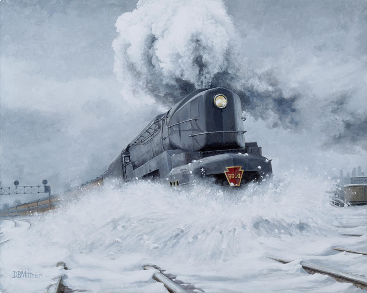
(Note: You can find the above painting for sale at fineartamerica.com if you click here).
The Type A Oscillating-cam System, The Rotary-cam System, and the T1A with Walschaert’s Valve Gear
Although the T1 design was a bit more complex than a more conventional single expansion steam locomotive it was certainly not the fact that it had four cylinders instead of just two that was the cause of the mechanical issues that beset it. There were many four cylinder duplex locomotives serving on America’s railroads that had proven themselves to be reliable. Similarly across the Atlantic in France the use of compound double-expansion steam locomotives was largely the norm, and these three and four cylinder engines were also able to operate reliably. So it was not simply a case of four cylinders being the cause of trouble, there was another design problem of a quite different nature that caused the T1’s to spend more time in the workshop than they should have done, and that was the Type A oscillating-cam system, and the poppet valves it operated.
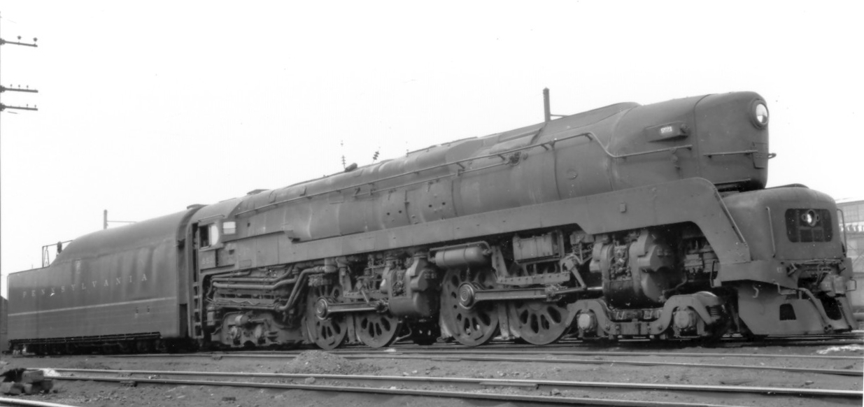
The Type A oscillating-cam system rotated back and forth, not through a full 360°. Each was set in motion by a miniature Walschaert’s valve gear system. This mechanism of itself was not the actual problem, but its location was. The front gear box was located under the “hood” of the shrouding on the pilot deck, behind the after-cooler, and between the air pumps. The location of the rear gear box was just as bad, being located behind the cylinder saddle, and oriented vertically between the frames. Although the gear boxes themselves were quite reliable the problem of high-speed wheel slip would cause damage and getting at them to do repairs was so difficult it might best be described as a “short straw job”, not a job a technician would like to have to do. The design-engineering decision to use poppet valves of itself proved to be a source of trouble that arguably outweighed the theoretical advantages such valves provide – that being steam delivery that is more precisely timed. However the poppet valves proved to be prone to failure and the high-speed wheel slip issue ensured that failure happened rather too often. To test whether a viable engineering solution could be found two locomotives were modified. Locomotive number 5500 was modified in July 1948 to a rotary cam valve system, and number 5547 was altered to conventional Walschaert’s valve gear in July 1949 creating the only T1A locomotive.
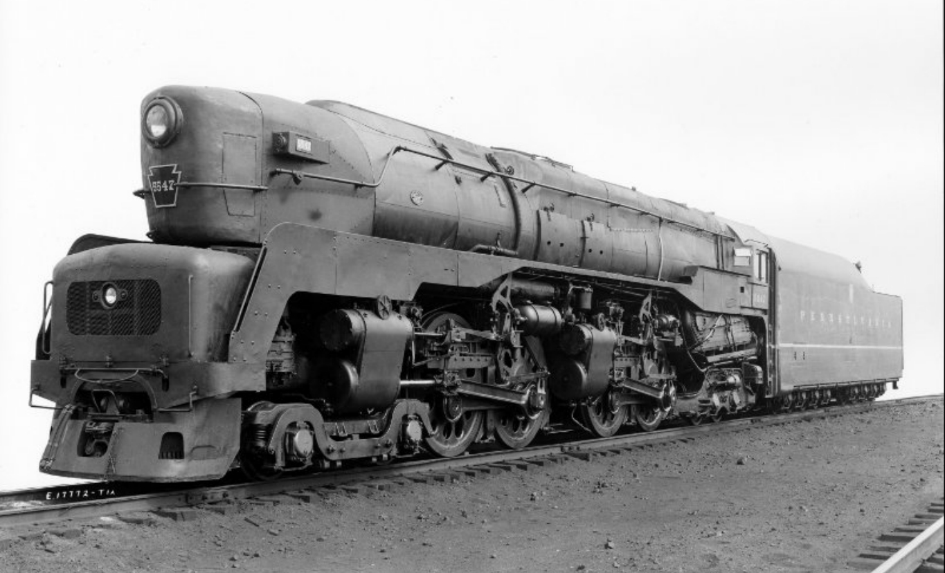
(Note: The above photograph and many more of Pennsylvania Railroad locomotives can be purchased from billspennsyphotos.com if you click here. This site has a number of excellent photographs of the sole class T1A, photographs that are very difficult to find:-right side, right quarter, left side, left quarter. ).
It is highly probable that the T1A locomotive #5547 proved to be a reliable and much easier to maintain engine. As can be seen in the above photograph the valve gear is located on the outside and is readily accessible. With the spring equalization set correctly and the old fashioned but reliable Walschaert’s valve gear the major weaknesses of the original T1 design were both addressed.
A Short Service Life
The Pennsylvania T1 had a short service life: their initial teething troubles sealed their fate and yet it is likely that even if they had all worked perfectly from the start they still would have been relegated to the scrap heap. Certainly over on the New York Central the Niagara was proven to be at least if not more efficient than the diesel locomotives it was competing with, and yet they too were all scrapped. The Pennsylvania Railroad President Martin W. Clement, announced in early 1948 that by May all their East-West passenger trains would be using diesel power, and the railroad lived up to that statement. The T1 locomotives were relegated to lesser duties and then progressively retired and sold for scrap between 1951-1955, with the last being towed to the scrap-yard in 1956.
The T1 was almost certainly the quickest steam locomotive the world has ever seen, although none of its high speed runs above 120mph were ever officially measured. The British established an official run with an A4 locomotive named “Mallard” hauling a dynamometer car and six coaches up to a speed of 126mph, which it held momentarily. But if the Pennsylvania Railroad technician who claimed he’d observed a T1 at around 140mph was correct then the T1 was a much faster locomotive.
Specifications
| Principal Dimensions by Steve Llanso of Sweat House Media | |
| Class | T1 |
| Railroad | Pennsylvania (PRR) |
| Country | USA |
| Whyte – Wheel Arrangement | 4-4-4-4 |
| Number in Class | 52 |
| Road Numbers | 5500-5549 |
| Gauge | Std |
| Number Built | 52 |
| Builder | Several |
| Year | 1942-1946 |
| Valve Gear | Franklin poppet |
| Driver Wheelbase (ft / m) | 25.33 / 7.72 |
| Engine Wheelbase (ft / m) | 51.92 / 15.83 |
| Ratio of driving wheelbase to overall engine wheebase | 0.49 |
| Overall Wheelbase (engine & tender) (ft / m) | 107 / 32.61 |
| Axle Loading (Maximum Weight per Axle) (lbs / kg) | 71,680 / 32,514 |
| Weight on Drivers (lbs / kg) | 279,910 / 126,965 |
| Engine Weight (lbs / kg) | 502,200 / 227,794 |
| Tender Loaded Weight (lbs / kg) | 442,500 / 200,715 |
| Total Engine and Tender Weight (lbs / kg) | 944,700 / 428,509 |
| Tender Water Capacity (gals / ML) | 19,200 / 72.73 |
| Tender Fuel Capacity (oil/coal) (gals/tons / ML/MT) | 42.60 / 38.70 |
| Minimum weight of rail (calculated) (lb/yd / kg/m) | 117 / 58.50 |
| Driver Diameter (in / mm) | 80 / 2032 |
| Boiler Pressure (psi / kPa) | 300 / 20.70 |
| High Pressure Cylinders (dia x stroke) (in / mm) | 19.75″ x 26″ / 502×660 (4) |
| Low Pressure Cylinders (dia x stroke) (in / mm) | |
| Tractive Effort (lbs / kg) | 64,653 / 29326.14 |
| Factor of Adhesion (Weight on Drivers/Tractive Effort) | 4.33 |
| Firebox Area (sq ft / m2) | 490 / 45.52 |
| Grate Area (sq ft / m2) | 92 / 8.55 |
| Evaporative Heating Surface (sq ft / m2) | 4209 / 391.03 |
| Superheating Surface (sq ft / m2) | 1430 / 132.85 |
| Combined Heating Surface (sq ft / m2) | 5639 / 523.88 |
| Evaporative Heating Surface/Cylinder Volume | 228.28 |
(Data courtesy steamlocomotive.com. To see the full table click here).
Will we ever find out for sure just how fast a T1 could go? Hopefully we will because The T1 Trust has been established to build a new T1 locomotive. The work has been progressing well with 28.1% of the construction completed and USD$675,000 raised so far. It is hoped that the locomotive will be completed by 2030.
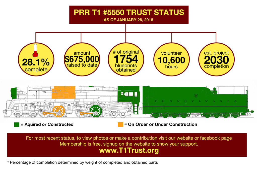
The intention is to build a new number 5550 locomotive similar to the modified locomotive number 5500 which was modified in July 1948 to a rotary cam valve system. The new locomotive is intended to be built as far as possible in accordance with the original design but with modern improvements where necessary or desirable. We wish them all success, and hope to still be around to see the project completed.
You will find The T1 Trust website if you click here.
There are various items for sale and you can contact them if you would like to make a donation large or small.
So the “missile of the rails” may yet run again to delight steam locomotive fans old and young.
The Pennsylvania Railroad’s T1 was probably the closest thing to a rail going Ferrari ever created. It was built during and just after the World War II era, a time when people looked forward in hope to a bright and prosperous future, in a world set free from tyranny and oppression. It was perhaps the greatest piece of railroad engineering and industrial art ever created.
Editor’s note: We are always looking to improve our content so if you have additional information that you think might be useful please feel free to contact us via our Facebook page.
(Feature image of a T1A duplex at the head of this post courtesy prrsteam.pennsyrr.com).
Jon Branch is the founder and senior editor of Revivaler and has written a significant number of articles for various publications including official Buying Guides for eBay, classic car articles for Hagerty, magazine articles for both the Australian Shooters Journal and the Australian Shooter, and he’s a long time contributor to Silodrome.
Jon has done radio, television, magazine and newspaper interviews on various issues, and has traveled extensively, having lived in Britain, Australia, China and Hong Kong. His travels have taken him to Indonesia, Israel, Italy, Japan and a number of other countries. He has studied the Japanese sword arts and has a long history of involvement in the shooting sports, which has included authoring submissions to government on various firearms related issues and assisting in the design and establishment of shooting ranges.
